This will show you the way to program an STM32F1xx series microcontroller with the Arduino IDE (integrated development environment).
Hardware needed:
- ST-link V2 – USB SWD (serial wire debug) programmer
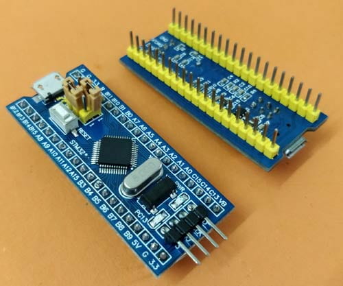
- STM32F1xx series microcontroller based board (i.e. “Blue Pill”)
- Hook up wires
Software needed:
- Arduino IDE – Latest
- ST-link utility (Includes drivers)
Installing the board into the Arduino IDE:
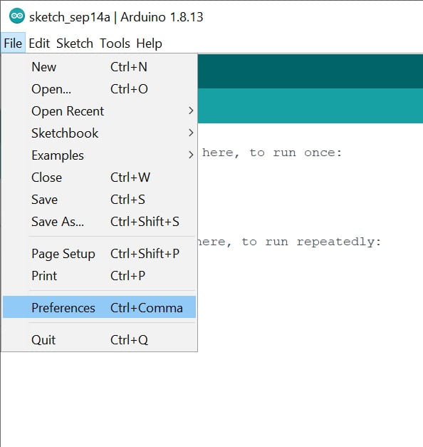
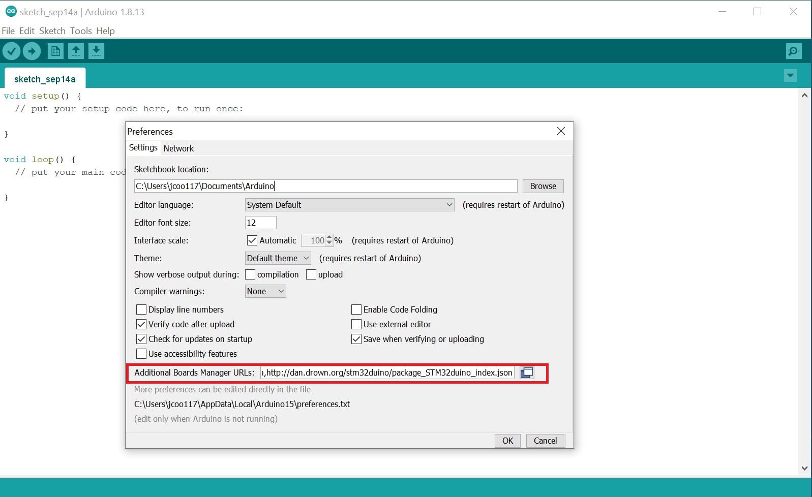
In the Arduino IDE, go to “File > Preferences”. Add the following link to the “Additional Boards Manager URLs” text box. Click the icon to the right to show a multiline textbox.
http://dan.drown.org/stm32duino/package_STM32duino_index.json
Click “OK” to close the preferences window.
Next, go to “Tools > Board > Board Manager”, wait for the list to download and search “STM32F1”. Install the “STM32F1xx/GD32F1xx boards” package.

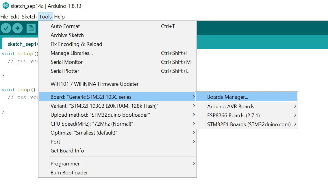
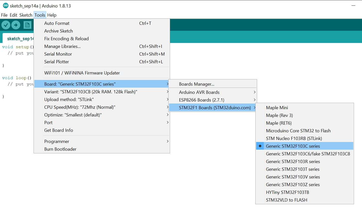
Select the correct microcontroller and “ST-Link” as the Upload method.
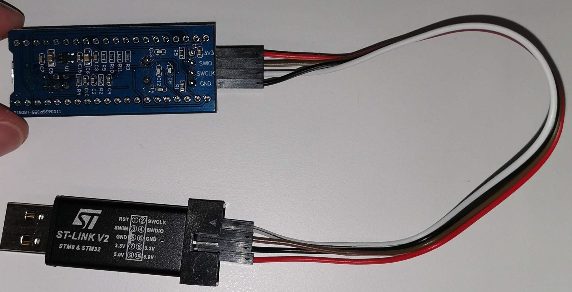
Connect the ST-Link V2 programmer to the STM32 board.
3.3V > 3.3V
SDWIO > SWDIO/SWIO/SWO
SWCLK > SWCLK/SCLK
GND > GND
Testing the setup
In the Arduino IDE, Click “File > Examples > A STM32_Examples > Digital > Blink”

On the “Blue Pill” board the LED is connected to PC13, so in the blink example, the output pin will need to be changed from PB1 to PC13 in all 3 locations for the LED to blink.

A good tutorial for this board can be found here by Alselectro. It also describes how to program with serial.
Troubleshooting:
If for some reason the ST-Link can’t find a device, remove both the BOOT selection jumpers just behind the USB port and try programming again. Reinstall the jumpers in position 0 after programming to set the board back into run mode.