This brief tutorial gives some tips for working with electronic circuits and covers some common issues beginners can have.
Where do you want to start?
Contents
What is electricity and why does it need a circuit
The circular path, which is always required to get electricity to flow and do something useful, is called a circuit. Watch here
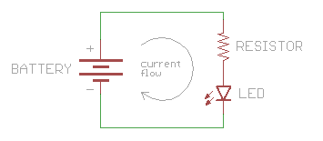 When we are connecting different components to our projects they will always need a positive (red wire) and a negative (black wire) connection to the battery or power supply. This is often accompanied by one or more data lines that extend to the micro-controller which is the brains behind your IoT device.
How to select components for a design
Firstly you may need to find the technical term for the component you need. For example, if you wanted to measure the air pressure you would need to add a Barometric sensor or movement that would require an accelerometer component. Asking a tech or a google search should get you started.
A Web Application such as TinkerCad or Circuito is often the next step where you can select from common components and drag and drop them into an automatically generated circuit diagram.
There are other factors you need to consider when choosing components such as size, price, sensitivity, life span, or strength of a motor. This selection process may need to be constantly used as you move through the design steps. Some factors that will always need to be considered will be cost, size, and power consumption. But others will be specific to the component in question such as torque and speed for motors and sensitivity and range for sensors.
If you are using a web application to start off with, it should have all the data you need in the component’s datasheet which is found in the BOM or on a google search.
If you limit yourself to the components we have at the Fablab it will be a faster process to prototype. See our component lists here
Building a circuit prototype
This step is assembling the components together into a working configuration. It may not be pretty but it should be wholly or partly functional to test aspects of the system.
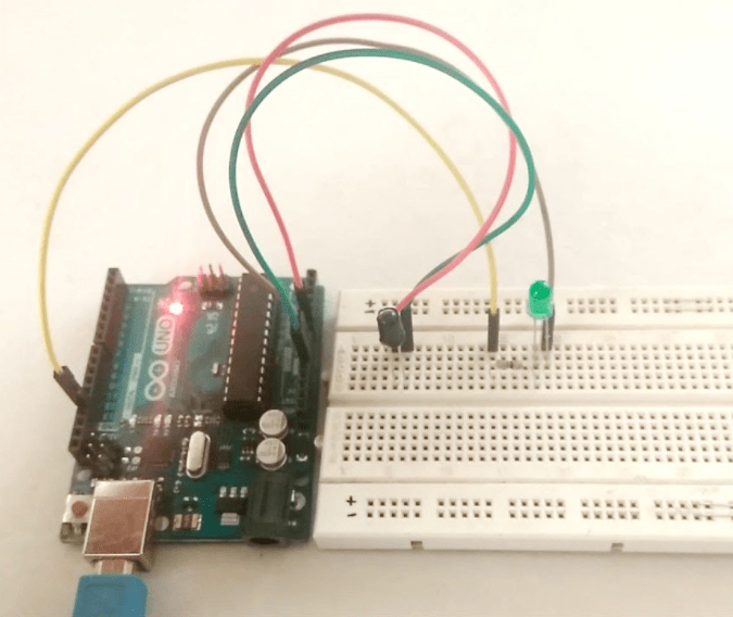 This is usually done with breadboards (a quick wiring system), development boards (circuit boards designed for testing) or in some cases with software. Ideally, the software solutions simulate the system also but these can be hard to use or with limited capability. Sometimes it’s easiest to use software such as Circuito.io to help with wire connections for you to follow when prototyping on a breadboard.
Once you have tested the system on a breadboard you can either directly solder wires to the components if components are distributed throughout the device or design a printed circuit board that can be manufactured in the Fablab or ordered from a web service such as jlcpcb.com or pcbway.com.
Helpful formulas, software and web apps
From Circuito Breadboard to Circuit Board to Prototype
Designing your electronic project will usually start with choosing the components that will perform the sensing, computing, displaying or transmitting that you require.
If you don’t know what a device is called just google “How do I measure …….?” So when you have made a list of components the device requires, open up a Circuito.io sketch and begin by choosing your Microprocessor, the brains behind your device. (For IOT projects where data needs to get onto the web it’s good to choose a Microprocessor that has its WiFI or bluetooth built in.)
With Circuito you can just drag and drop components into the sketch and it will wire up a breadboard, populate a Bill Of Materials and create sample code to test each component. It even includes the Arduino software libraries you might require to use each component.
So you have just created your device by dropping in the components into a Circuito.io sketch. Now how do you develop that into an actual working prototype…
Firstly, do these components actually fit into your design.. to check on the sizes of the components, investigate the bill of materials and download the datasheet. The datasheet should contain all the technical aspects engineers require when using the device. For us we mainly will look for the dimensions and power consumption.
Power consumption is often overlooked when components are selected and even if the device is powered by a wall socket you will need to select a power supply to convert the wall power into the correct power for the device. This power supply will only be able to supply your components with power up to its max current rating in Amps. Most sensors and microcontrollers can be run from a single phone charger type power supply. However when you include, motors, lights, pumps, and displays they may need more power than expected. Similar to a cost budget you can create a power budget by adding the current draw (in Amps) of al the components together. This should come in under the power supply limit and also give you battery live estimations if you are running from battery power. More information on power and how Amps, Volts and Watts all interconnect in the next section.
The next step is to assemble your circuit on a breadboard and test it. It’s often a good practice to add components one at a time to more easily spot and solve mistakes. This may not be possible if there is a pandemic so this step may have to be skipped.
To move to the next stages you will need to remove the breadboard from your circuit and create a wiring diagram. It can look a lot like your breadboard diagram. The main differences are where the wires are branching out to connect multiple places to one another. There will almost always be branches to and from ground and positive power.
Sometimes it’s good the think of the power circuit like power rails where each component gets its power by connecting to both rails.
To find out more on how a breadboard works, check out this post from Sparkfun.
Voltage, Current, Resistance and Power fundamentals
- Voltage – Volts (V) can be thought of as how fast the flow is, or speed of a river.
- Current – Amps (A) can be thought of as how much flow, or width or a river.
- Resistance – Ohms (Ω) is the restriction to current flow, or a narrow section of a river.
- Power – Watts (W) how fast and how much, or how much energy a river flow has
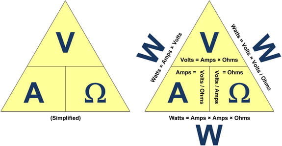
The following triangle formula diagrams explain the relation between and how to calculate voltage, current, resistance and power. At Least two other values need to be known to calculate another property.
Example: A 14V battery is powering a heater of resistance 100Ω. The Current (Amps) can be calculated by using the triangle equation. We want ‘A’, so we need the other two values which are ‘V’ and ‘Ω’ which are known. With the triangles, anything below a value is the denominator with the upper value being the numerator (divided by).
(Cook Appendix A)
Completing the circuit
- Energy/power/current needs to go somewhere. As the term “circuit” suggests, it must come back around in a loop. Commonly this is the positive power connecting through several components to the negative power (0V or GND). Basics outlined well here from SparkFun.
- Need to have an in and an out. And usually, we keep the positive wires red and the negative wires black. This gives a universal way to quickly check that a circuit is indeed a circuit.
Voltage of components
All components are designed to work in a certain voltage range and should always be checked before powering on circuits. These ratings can be found on the component datasheets (usually found by Googling the part number).
For example, Microcontrollers are generally 3.3v or 5V and can only work with other components with the same or lower voltage signals or the devices can be destroyed. However, there are converter modules that can allow 3.3V systems to work with 5V systems.
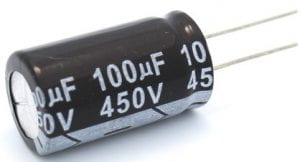
Capacitors also have voltage ratings which should be checked before turning on a system. The rating is usually on the side of the case.
Power requirements and current draw of components
It’s a good idea to do some basic calculations early on in the design process to determine an approximate power draw from the system and battery size if needed.
It’s also important to understand that all circuits are not 100% efficient so its best to round up. When converting different voltages, from DC to DC a typical conversion efficiency is 70%, or 95% for a DC to AC mains power inverter.
The best way of working out what the system uses is adding up the power(watts) of all the devices while taking in account any losses/additional power required for voltage conversion if necessary.
For example:
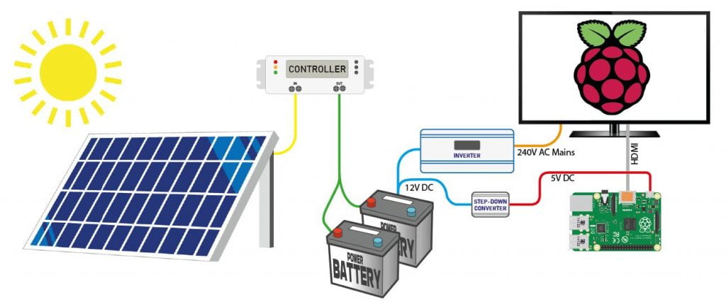
The power requirements of a 12V solar-charged battery system with a 55” TV and a Raspberry Pi 4B, which needs to be active and powered for 6 hours every day.
A standard 55” TV uses about 143W of power, to go from battery voltage through an inverter you lose up to about 5% power, which is 143W x 5% = 7.15W additional power, 143 + 7.15 is about 150W draw. The raspberry Pi 4B uses about 15W at 5V DC, so it will need a Dc to DC converter to get from 12V to 5V which will require an additional 30% for efficiency losses, 15W x 30% = 4.5W, 15W+ 4.5W is about 20W. This gives an approximate total power draw of 20W+ 150W = 170W load on the 12V battery system during operation
Calculating approximate battery life
Battery capacity is listed in Amp Hours (Ah) or milliamp Hours (mAh) and is the theoretical maximum amount of Amps a battery can give in an hour period until it is dead. For instance, a typical Lithium-Ion battery in a 18650 cylindrical size is about 2500mAh (or 2.5Ah), which means it can provide 2.5 amps for 1 hour maximum.
So, to calculate the approximate battery time for our TV example which needs to run for 6 hours on a 12V battery, the load of 170 watts needs to be converted into a battery capacity in Amp Hours. From electronics basic equations Power, Watts is Volts x Amps, (W=VxA ). The Voltage of the battery is 12V and the Wattage is 170W so we can work out the Amps. The equation can be rearranged to give Amps, A = W divided by V, (A=W/V). A=17012=14.17A.
To get the Amp Hours it is just the amps for the number of hours; 14.17A x 6h =85Ah. This means the battery needs to be greater than 85Ah at a minimum! A factor of safety should also be used so the battery size should be at least 100Ah and 12V.
Solar panels for charging batteries
For working out solar panel size it’s best to work off the worst-case conditions because if conditions are good and more power is produced, the charging system will just stop charging the batteries. The average usable daylight hours in winter, taking into account and excluding morning and afternoon times where the sun does not hit the solar panel at the correct angle, is about 5 hours (Estimates from Daylight Hours). The system will need to collect and store more than what would be used during the designed on time. This is 170 watts for 6 hours = 170W x 6h = 1020 Wh (Watt-hours) that needs to be collected in 5 hours. From this we can work out how many watts the solar system needs to collect on average; 1020Wh / 5h = 204W minimum average on a sunny day. But on a cloudy day, solar power may only produce 10% – 25% of a sunny day. This would bring the minimum rating of 204W (10%) to 204W x (100%/10%) = 204W x 10 = 2040W minimum average on a cloudy day in winter.
A commonly available solar panel size is 300W (1.8m x 1m each). That means the system would need at least 7 x 300W panels to charge on a cloudy day (2040W/300W = 6.8). If that system gets 5h usable full sun daylight hours in winter, that is approximately 2100W (7 x 300W) for 5 hours = 2100W x 5h = 10500Wh. But only 10% of that on a cloudy day = 1050Wh, which is still slightly above the minimum required to charge the batteries. If we assume that is stored perfectly in a battery, the approx run time would be 1050Wh / 170W = 6.1h powered time. As the design only needs 6h the system should theoretically always be charged but to provide a good factor of safety it would be good to add another solar panel. 8 x 300W panels would require an area of 1.8m x 1m x 8 = 14.4m2.
Useful prototyping Apps
- Circuito.io
- Wires everything for you
- Not all components
- Produces a BOM (Bill of Materials)
- Tinkercad.com
- Limited components
- Arduino code simulation
- Fritzing.com
- Paid
- Lots of components
