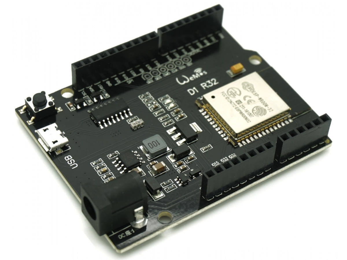
An Esp32 micro-controller in an Arduino Uno footprint.
This is a powerful little development board with WiFi and Bluetooth capabilities. Best of all it’s easy to program using the Arduino IDE.
Just follow this tutorial here for the full step-by-step instructions on programming ESP32 with Arduino IDE.
Some more info on adding boards to the Arduino IDE is detailed here.
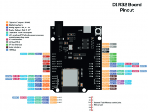
Below is the pinout for the board.
Be aware that the pins Arduino use are the GPIO numbers. i.e. GPIO1 would just be 1. Also, some pins are input only such as GPIO34, 35, 36, and GPIO39.


Thank you for sharing the pinout!
I am a bit puzzled about the functionality of pin below:
> software pullup after boot with dim Red SMT LED at:
> pin24 -N GPIO-02 – ADC12/Touch2 (default pulldown)
In the case of the ESP32 Uno R3 board, which mimics the pin layout of Arduino Uno R3, I am forced to use a shield having this pin used as ADC0 in Arduino world.
So GPIO02 will be redefined as an ADC… a pot will be connected to this pin, to provide a variable voltage.
The question is… what happens with LED behaviour ? Will the LED pullup circuitry influence the ADC operation ?
I don’t know what your circuit has and how the LED connects. But it’s best not to use GPIO2 or 4 for any ADC reading as they are shared with the HSPI bus which can upset results and sometimes cause issues with programming if anything is connected.
Thank you for reply.
Is not my circuit, but an true Uno shield that was been designed to use the analog pins zero and one, as they are in an Uno design, as ADC !
I don’t understand why the creators of this “Uno” board didn’t mapped the ESP32 ADC accordingly, as 0…7, instead this mixture that make a mess maintaining compatibility of code…
I would expect A0 pin to be the same for both, as are SCL/SDA for I2C, else what sense has the claim that is a Uno pinout ?
Yeah, I agree it is confusing they designed it with an Uno form factor when the chipset does not have the same pin functions, so not all shields are compatible.