Arduino code Converting images into byte arrays for mono-colour screens with microcontrollers. Best suited for static splash screens or basic animation on small screen sizes when using the Adafruit_GFX library with Arduino.
Workflow:
- Find the specifications of the screen the graphics are to be used on. Such as 128×64 pixels
- Design a graphic to fit within the screen space.
- Setup a new document in a graphical design software with the artboard dimensions and create the design in black and white.
- Save the design file as PNG with the correct dimensions the artboard was set up to.
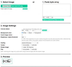
- Go to the free website app http://javl.github.io/image2cpp/ and upload the PNG file of the design. Choose the image settings to match your design (canvas size set to the screen size, background to match the design for easy separation, and scaling to get the desired output. There is a preview window below showing the output)
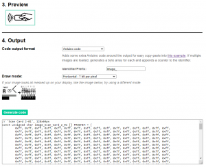
- Select the “Code output format” as Arduino Code. “Identifier/prefix” is the prefix of the byte array. For single colour screens select one byte per pixel as most screens render horizontally row by row, select “Horizontal – 1 byte per pixel”. Then click “Generate code”.
- In the text box below the “Generate code” button, the byte array data should be shown.
- Copy the contents into your Arduino sketch, either at the top or in a separate tab.
Example:
Using a 0.96″ OLED display with 128×64 pixels.
Needs to show an RFID symbol or icon to show it’s ready to accept scanning. This was downloaded from the internet and scaled to fit a 128×64 pixel artboard in illustrator then saved as a PNG.

In the app http://javl.github.io/image2cpp/ the file was loaded and settings set such that the preview was showing the desired output.
The output was set for Arduino Code, Prefix was “image_” and draw mode was “Horizontal – 1 byte per pixel”. Also in at the bottom of the output window is the size in bytes of the array which is needed for some drawing functions.
The output code was copied into a test sketch which can be downloaded here. It includes the Arduino code for this example.
The byte array was formatted differently to work with my demo in that “const unsigned char epd_bitmap_Scan_Card_2_01 [] PROGMEM = { ” was changed to “static unsigned char image_Scan_Card_2_01 [1040] = {” to define the size of the array. It was also placed in another, included file (tab) of the Arduino sketch called “images.h” to make the main code cleaner.
Below a video can be seen of the example running. (the video camera was interfering with the refresh rate of the screen )
![]()


